

Technology

Why DC Load Bank Test Results Drift More Often Than People Expect
A DC Load Bank is supposed to make troubleshooting clearer, not harder. But in day-to-day service work, test results often start to drift just enough to create doubt. One discharge test looks normal, the next one shows unexpected voltage sag. Current appears slightly off from the setpoint. Temperature rises faster than it did in earlier records, even though the battery string or DC source has not changed much.
This kind of drift usually does not come from one dramatic failure. More often, it builds from small errors: a sensor aging out of tolerance, a loose lug adding resistance, a fan path partially blocked by dust, a current shunt installed correctly years ago but no longer verified. For after-sales maintenance work, that matters. If the load bank itself is drifting, the team may end up diagnosing the wrong component, repeating inspections, or replacing healthy parts.
In resistive and capacitor-related power equipment, stable test conditions are everything. Companies that build this kind of equipment, including manufacturers like Sunwin with product lines covering resistive load banks, rack mounted units, electronic load banks, liquid cooling load banks, portable load banks, battery load testers, grounding resistor cabinets, and capacitor banks, know that measurement stability is not just about the resistor element. It is also about wiring integrity, thermal behavior, control logic, and maintenance discipline over time.
The first place to look: measurement chain errors
When a DC Load Bank result drifts, the measuring chain is usually the smartest starting point. That includes current shunts, Hall sensors if fitted, voltage sensing leads, temperature probes, display modules, and the data logging path.
Shunts are especially easy to overlook because they are passive devices and tend to look fine even when they are no longer behaving ideally. Oxidation at terminals, uneven tightening, heat cycling, or replacement with a non-matching part can all change the effective reading. The drift may be small on a short test and more obvious during extended runs when temperature rises. If field data shows a current deviation that slowly increases over the test duration rather than appearing instantly, thermal influence on the measuring chain is a realistic suspect.
Voltage sensing issues can be even more misleading. A poor sense connection does not always produce a dramatic fault. It can simply introduce unstable readings, especially if the cable routing runs near switching devices, blower motors, or long DC conductors carrying high current. In practice, if the displayed voltage moves more than expected while the source itself appears steady on a reference meter, check the sensing path before questioning the power system.
Practical fix
Use an independent calibrated meter to verify voltage and current at the load bank terminals, not only on the controller display. If the external measurement is stable and the load bank display is not, isolate the problem into the internal measurement path. Re-torque connections, inspect shunts for discoloration or overheating history, and verify whether the installed sensor matches the original electrical specification.
Connection resistance is a bigger problem than many reports admit
One of the most common causes of drifting results in DC discharge testing is simple connection resistance. Service teams often focus on the battery, rectifier, or DC bus condition and give less attention to the cable set and connection hardware used during the test. That is a mistake.
A slightly loose terminal, a cable lug with surface contamination, or a connector that has been mechanically stressed over repeated field jobs can create localized heating. Once it warms up, resistance changes. That affects current sharing, terminal voltage, and sometimes even the protective behavior of the load bank. The result may look like source instability, when in reality the test setup itself is drifting under load.
Portable load banks are particularly exposed to this because they are moved, unpacked, reconnected, and sometimes used in less-than-ideal environments. Rack mounted or fixed units usually have fewer handling-related issues, but they are not immune. Long-term vibration, cabinet maintenance work, or retrofits can leave behind one weak connection that only shows up at higher current.
What helps in the field
Do not rely only on visual inspection. A connection can look acceptable and still be electrically poor. Check for temperature rise across terminals during load application, compare voltage drop across similar connection points, and pay attention to any reading drift that starts after the first few minutes rather than at test startup. That pattern often points to resistance increasing with heat.
Heat changes resistor behavior, airflow changes heat
Because a DC Load Bank is fundamentally converting electrical energy into heat, thermal stability directly affects test stability. Resistive elements can shift as they warm, and although that behavior is expected within design limits, it becomes a problem when cooling performance is no longer what it was when the unit was commissioned.
Blocked airflow, worn fans, dust buildup, damaged ducting, and uneven internal heat distribution can all push resistor elements into a different operating range. Then the actual load does not match the intended load as closely as it should. In a liquid cooling load bank, the same principle applies through another path: coolant flow, heat exchanger condition, pump performance, and thermal sensor feedback all affect stability.
This is one reason two tests using the same model can behave differently in the field. The nameplate may be the same, but the thermal condition is not. If one unit has a clean cooling path and another has partially restricted airflow, the drift under sustained load can be noticeably different.
Observed symptom Likely thermal-related cause Practical check Current slowly falls during long test Resistor heating, airflow reduction, or sensor drift at elevated temperature Inspect fan operation, air path cleanliness, and compare cold vs warm readings Unexpected hotspot alarms Blocked ventilation or failing thermal probe Check airflow balance and confirm probe reading with external measurement if possible Load step values inconsistent Thermal stress affecting contactors or resistor section switching Review switching sequence and inspect contact wear under heat Calibration drift is real, and it is often confused with system degradation
If a load bank has been in service for years and test values are drifting without any obvious electrical fault, calibration status should move much higher on the checklist. This is especially true where the unit is used to evaluate battery performance, because maintenance teams tend to compare new results against historical records. If those records were built using a differently calibrated state, the trend line can become misleading.
The trap here is subtle. A load bank that is only slightly out may still produce repeatable but inaccurate data. That is worse than a unit that fails outright, because it encourages false confidence. If battery reserve time appears to be declining in a smooth pattern, the conclusion may be “battery aging.” Sometimes that is correct. Sometimes the load current being applied is no longer what the operator believes it is.
Calibration intervals depend on usage intensity, environment, and internal component design, so there is no universal number that fits every site. What matters is consistency: compare readings against traceable instruments at defined intervals, and do it under conditions that resemble actual operating load rather than a quick bench check only.
Control components and switching devices can introduce “soft” drift
Not all drift comes from sensors or resistors. In stepped load banks, relays, contactors, and control boards may create partial or inconsistent load application. A contactor with worn contacts may still close, but not cleanly every time. One resistor branch may intermittently contribute less than expected. On an electronic load bank, current regulation behavior can also shift if the control loop is affected by component aging or unstable feedback.
This kind of issue often shows up as test-to-test inconsistency rather than a steady offset. One day the unit holds target current well, another day it hunts slightly around the setpoint or settles at a different value after warm-up. If the maintenance team only records final values and not the load profile over time, this may go unnoticed for months.
A useful field habit is to log the load response during step changes, not just the average reading. The shape of the response tells you a lot. A slow settle, overshoot, or inconsistent step contribution often points to control or switching hardware rather than the power source under test.
Test environment matters more with DC than many people expect
Ambient temperature, ventilation, cable routing, electromagnetic noise, and even floor layout can affect repeatability. In battery rooms or rectifier spaces, you may have limited cooling air, long cable runs, and nearby high-current conductors. All of these can influence readings or thermal conditions.
Capacitor-related installations add another layer of caution. Although the article focuses on DC Load Bank testing, sites that also include capacitor banks or power quality correction equipment can have switching transients and grounding details that complicate measurement behavior. Usually that does not make the load bank inaccurate by itself, but it can create noise, unstable references, or misinterpretation of what the readings mean in a mixed electrical environment.
If drifting results only happen at one site and not another, do not assume the load bank is defective. Compare environmental conditions, setup distance, ventilation path, and grounding arrangement before making that call.
A practical troubleshooting sequence that saves time
When test results drift, chasing every possibility at once usually wastes a service visit. A more efficient sequence is:
- Verify the source with independent instruments.
- Check cable sets, lugs, and terminal torque under actual load conditions.
- Review cooling performance and compare cold-start versus warmed-up readings.
- Inspect sensing components and calibration records.
- Observe switching behavior or current control response during step changes.
- Only after that, move toward deeper controller or component replacement decisions.
This order works because it starts with the most common and most field-relevant causes. In real maintenance work, loose connections and thermal problems appear far more often than exotic controller failures.
Preventing drift is mostly about routine discipline
Stable DC Load Bank testing does not depend on one perfect component. It depends on repeatable setup, verified measurement, clean cooling paths, and timely recalibration. Teams that get the best long-term results usually do a few basic things well: they use the same test method each time, document ambient conditions, keep connection hardware in good condition, and do not skip verification just because the unit “still seems to work.”
If your results have started to drift, the fix is often less dramatic than expected. Start with the measurement chain, then the connection points, then the thermal path. In many cases, that is where the answer is hiding. And if the unit is part of a broader fleet that includes portable, rack mounted, resistive, or electronic models, keep maintenance records by equipment type. Drift patterns are not always identical across designs, and treating them as if they are can create a lot of unnecessary confusion later.
Why DC Load Bank Test Results Drift: Common Causes and Practical Fixes
For technical evaluators planning high-density test environments, a Rack Mounted Load Bank must balance power density, thermal management, safety, and serviceability without compromising rack integration. This article examines the key design considerations that impact performance, reliability, and ease of deployment, helping you assess the right solution for demanding test applications.
Why rack-mounted designs are being used more often
In many test labs, telecom rooms, data center validation spaces, and power electronics environments, floor space is already committed before a load test even begins. That is where rack mounting becomes more than a packaging choice. It is a way to place test capability close to the equipment under validation, reduce cable runs, and keep the test setup aligned with existing infrastructure.
The appeal is straightforward: a rack-mounted unit can be integrated into the same mechanical and electrical ecosystem as servers, UPS modules, battery systems, DC distribution panels, or inverter test benches. But the rack format also introduces constraints that are easy to underestimate. A load bank that performs well on paper can fail in practice if airflow is poor, heat rejection is not matched to rack conditions, or maintenance access becomes impractical once installed.
For evaluators, the real question is not whether a Rack Mounted Load Bank fits in a rack. It is whether it can deliver repeatable load performance under continuous thermal stress while remaining safe, accessible, and compatible with the test environment.
Power density is useful only when the rack can support it
High-density test environments usually push for as much load capacity as possible per rack unit. That pressure makes sense, but power density should never be evaluated in isolation. The true bottleneck is often the rack’s ability to remove heat and support cable routing, breaker protection, and airflow separation.
A dense resistive load bank generates heat by design, and that heat must be managed in a predictable path. If the airflow path is obstructed, the unit may derate early, trigger thermal protection, or create hot spots that shorten component life. The evaluator should look beyond nameplate power and ask how the rated capacity is derived: at what inlet temperature, with what airflow rate, and under what duty cycle.
One common mistake is to compare models only by kW per U. That metric is useful, but incomplete. A more meaningful comparison includes usable continuous power, maximum allowed inlet temperature, fan redundancy, and whether the unit can maintain output without requiring the rack itself to be heavily modified.
Thermal design is usually the deciding factor
In a Rack Mounted Load Bank, thermal design is not a supporting feature; it is the core of the product. The resistive elements, control electronics, internal wiring, fans, and connectors all contribute to the heat profile. If any one of those elements becomes the weak link, the full system loses reliability.
Airflow direction matters. In mixed rack environments, front-to-rear cooling is often preferred because it aligns with common rack standards and simplifies integration. Even so, compatibility with the surrounding equipment must be checked carefully. A load bank that exhausts warm air into the intake of nearby sensitive electronics can create a hidden system-level issue even if the load bank itself is operating within specification.
Evaluators should also examine whether the design accounts for local thermal gradients. High-power elements placed too close to temperature-sensitive components can reduce service life. Thermal sensors should be positioned where they can detect real stress conditions, not only average internal temperature.
In practice, the best designs do not simply “cool the unit.” They keep the load profile stable under repeated cycling, partial loading, and varying ambient conditions. That is especially important in validation environments where test results must be reproducible.
Rack integration is a mechanical and operational issue
Mechanical fit is often treated as a checklist item, but rack integration affects daily usability. Weight distribution, rail strength, front-panel access, and cable bend radius all influence whether the equipment is practical in a real lab or test room.
Heavy units mounted in the upper part of a rack can create handling risks and structural concerns. A practical design should support stable installation without requiring awkward lifting or frequent removal of neighboring equipment. If maintenance requires extracting the full unit from the rack, the labor impact becomes significant over time.
Front-access controls are useful, but only if they remain visible and usable once the unit is installed. Likewise, rear connections should not force excessive cable strain or block exhaust paths. In dense environments, the physical location of power terminals can determine whether the system is maintainable or merely installable.
For this reason, technical evaluators should review not just rack units and dimensions, but the entire service envelope: how the unit is mounted, how airflow is preserved, how cables are routed, and how a technician reaches critical components during inspection or replacement.
Control accuracy matters more than many buyers expect
Load banks are often discussed as if their only job is to consume power, but testing environments usually need controlled and repeatable loading. That means step resolution, response time, and stability matter. If the control system introduces large jumps, poor repeatability, or delayed switching, the test data becomes less useful.
This is especially important where the Rack Mounted Load Bank is used for power supply validation, UPS burn-in, battery discharge testing, or inverter characterization. In those applications, the test objective is often not just “can it handle the load” but “how does the source behave under controlled and repeatable stress.”
Technical evaluators should check whether the load steps are fixed or programmable, whether control is local or remote, and whether the actual switching behavior matches the intended test profile. A design that looks adequate in a specification sheet may still produce poor test fidelity if the control granularity is too coarse.
Protection features should match the risk profile of the test environment
Safety design in rack-mounted equipment is not only about preventing catastrophic failure. It is also about limiting nuisance trips, containing fault propagation, and allowing operators to respond quickly when conditions change.
Important items include overtemperature protection, fan failure detection, input overcurrent protection, proper grounding, and clear indication of fault states. In high-density racks, fault visibility is especially important because one failing unit can affect nearby equipment if the thermal or electrical environment is tightly packed.
It is worth checking whether protection is implemented at the unit level or assumed to be managed by external infrastructure. A robust load bank should not rely on ideal site conditions to stay safe. It should behave predictably when airflow is reduced, ambient temperature rises, or the source under test behaves abnormally.
In environments where battery systems or DC power sources are tested, polarity handling, connector integrity, and discharge control become even more important. The protection concept needs to match the actual use case, not just the generic product category.
Serviceability is often underestimated during procurement
At the specification stage, service access may seem secondary. After deployment, it becomes one of the most important practical issues. Fans wear out, terminals need inspection, dust accumulates, and control boards may require replacement. If servicing the unit means taking the entire rack offline, the operational cost rises quickly.
Good serviceability usually shows up in small design choices: modular fan replacement, accessible filter paths, clearly labeled wiring, field-replaceable protection devices, and component layouts that allow diagnosis without dismantling the full system. These details are rarely prominent in marketing materials, but they are often what determine real uptime.
For test labs with limited maintenance windows, the ability to inspect or replace parts from the front side of the rack can be a major advantage. In some cases, a slightly lower power density is justified if it avoids repeated downtime and improves long-term availability.
Environmental assumptions should be verified, not accepted
Many load bank specifications are written around a set of standard assumptions that may not reflect the real site. Ambient temperature, altitude, humidity, dust level, and rack airflow all affect performance. If those parameters are not checked early, the selected system may need derating or modification after installation.
This matters most in high-density environments because multiple heat-generating devices already share the same air volume. A rack-mounted load bank may be technically compliant in isolation but still struggle when installed beside other thermal loads. The evaluator should ask how the unit performs in worst-case ambient conditions, not only in ideal lab conditions.
Where the environment is unstable or ventilation is constrained, additional thermal margin is usually worth more than a higher nameplate rating. In practice, a conservative design often delivers better uptime and less maintenance than an aggressively packed one.
Electrical interface details can make or break deployment
The electrical side of a Rack Mounted Load Bank deserves the same attention as the thermal side. Input voltage range, current rating, connector type, protection coordination, and grounding method all affect deployment speed and operational safety.
Mismatch here creates avoidable delays. If the rack is built for one electrical architecture and the load bank expects another, the project may require adapter hardware, additional distribution, or rework of the test bench. That is especially common in mixed-voltage environments where AC and DC testing coexist.
Clear labeling and robust terminal design are not minor details. In dense racks, technician error becomes more likely when wiring is crowded or access is limited. The better the electrical interface is designed, the lower the risk of misconnection and the easier it is to reproduce test setups across multiple sites.
Compliance and standards need context, not just a badge
For technical evaluators, compliance claims should be interpreted carefully. A declaration of conformity may be meaningful, but only if it corresponds to the actual deployment region, voltage class, and safety environment. Depending on the market, buyers may need to confirm alignment with relevant electrical safety and EMC requirements. Exact standard applicability should be verified for the intended application and jurisdiction, rather than assumed from a brochure.
What matters most is not the presence of a certificate alone, but whether the product’s design, documentation, and testing support the site’s regulatory obligations. If the load bank is going into a customer lab, a telecom facility, or an export project, documentation quality can be as important as technical performance.
Evaluators should request clear manuals, wiring diagrams, fault procedures, and maintenance guidance. A technically strong design becomes much easier to approve when the documentation supports safe integration and consistent operation.
Choosing the right design means matching the load bank to the test philosophy
The best Rack Mounted Load Bank is not necessarily the one with the highest rating or the most compact footprint. It is the one that matches how the environment actually operates. If the test program requires long-duration load runs, thermal stability may matter more than absolute density. If the lab changes test profiles frequently, control flexibility and service access may matter more than raw power.
For evaluators, a useful decision framework is simple: confirm the expected power profile, verify thermal headroom, check installation constraints, review protection behavior, and assess maintenance impact. If the product performs well in all five areas, it is likely to hold up in a demanding high-density environment.
In this category, the most expensive failure is usually not electrical failure. It is operational friction: a unit that is difficult to install, difficult to cool, difficult to maintain, and difficult to trust under repeat testing. That is why rack-mounted load bank selection should be treated as a systems decision, not just a component purchase.
For technical teams comparing options, the most useful question is often not “How much load can it absorb?” but “How much reliable test capability can it provide inside the constraints of this rack, this airflow path, and this maintenance model?” That is the level at which a Rack Mounted Load Bank proves its value.
Rack Mounted Load Bank Design Considerations for High-Density Test Environments
Resistive Load Bank Safety Risks Often Missed During Routine Testing
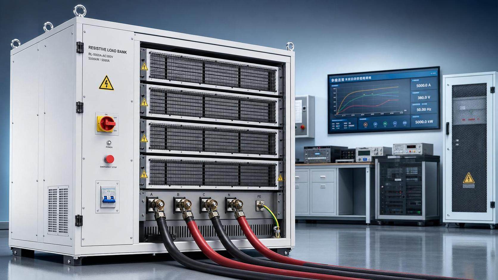
Routine testing can make a Resistive Load Bank feel routine. That impression is often misleading. Repetition builds familiarity, but it can also hide risk.
In many facilities, the same test setup runs for months without incident. Then one minor change triggers overheating, arc exposure, nuisance trips, or damaged equipment.
That pattern matters because a Resistive Load Bank handles high current, heat, airflow, and switching stress at the same time. Small errors rarely stay small.
For organizations managing reliability, compliance, and worker safety, the real issue is not only test execution. It is risk visibility before the test begins.
This article focuses on the safety gaps often missed during routine Resistive Load Bank testing and the practical controls that reduce exposure.
Why routine testing creates blind spots
The biggest safety problem is often normalization. When no recent incident exists, teams assume the existing process is already safe enough.
A Resistive Load Bank may pass electrical performance checks while hidden safety margins continue shrinking. Dust, loose terminations, fan wear, and heat damage progress quietly.
More importantly, standard checklists often confirm output values, not operating conditions. A good reading does not automatically mean a safe test environment.
This also explains why near misses repeat. Teams monitor current, voltage, and duration, but miss airflow obstruction, cable heating, or enclosure temperature rise.
Common blind spot patterns
- Using the same setup sheet after equipment relocation or site modification.
- Assuming cooling performance is unchanged because the fan still runs.
- Treating short-duration tests as low-risk regardless of step load size.
- Overlooking accessory components such as connectors, breakers, lugs, and grounding points.
Overheating risks that routine checks often miss
Heat is the most predictable hazard in a Resistive Load Bank, yet it is still one of the most underestimated.
Many teams verify that cooling fans start correctly. Fewer confirm whether airflow volume, duct clearance, and exhaust recirculation remain within safe limits.
A partially blocked inlet can raise internal temperatures long before external alarms activate. That creates slow insulation damage and uneven resistor aging.
Portable and rack mounted systems face an added problem. They are more likely to be tested in crowded electrical rooms with poor ventilation.
What to verify beyond fan operation
- Inlet and exhaust clearance against manufacturer requirements.
- Air filter condition, internal dust loading, and evidence of hot spots.
- Temperature trends across resistor elements, not just one sensor point.
- Ambient room temperature during peak load steps.
For liquid cooling load bank applications, the hidden risk shifts. Flow restriction, coolant quality, and leak detection become just as important as electrical readings.
Connection failures and grounding errors
A Resistive Load Bank rarely fails alone. Connection points usually show the first signs of trouble.
Loose terminations increase resistance, and increased resistance creates localized heat. That heat can damage lugs, insulation, busbars, and enclosure surfaces.
In actual operations, the risk grows after repeated transport, maintenance, or cable replacement. Torque values drift, surfaces oxidize, and unauthorized substitutions appear.
Grounding is another area where routine assumptions become dangerous. A connected grounding point is not the same as an effective grounding path.
High-risk connection issues
- Improper cable size for the intended current and test duration.
- Mixed connector types creating unstable contact pressure.
- Ground conductors attached to painted or contaminated surfaces.
- Repeated use of damaged cables with hidden conductor fatigue.
Thermal imaging after stabilization can reveal connection defects early. It is one of the simplest controls for Resistive Load Bank safety verification.
Control system and protection failures hidden by passing tests
A passing load test may still hide a failing protection layer. That is especially true when operators focus only on target kilowatt performance.
Interlocks, emergency stop circuits, overtemperature cutoffs, and alarm outputs can degrade gradually. They may appear normal until a fault forces them to respond.
This is why a Resistive Load Bank should never be evaluated only by load acceptance. Protection function testing must be part of the routine.
Electronic load bank configurations add another layer. Communication errors, control software changes, and sensor drift can change behavior without obvious visual signs.
Protection checks worth adding
- Verify alarm thresholds against documented setpoints.
- Test emergency stop response under controlled conditions.
- Confirm fan failure or overtemperature shutdown logic.
- Review controller event logs for intermittent faults.
Environmental and human-factor hazards
Not every safety issue sits inside the Resistive Load Bank enclosure. Many start in the surrounding work area.
Noise, heat discharge, restricted access, poor labeling, and rushed test schedules all increase the chance of procedural mistakes.
A temporary test area often lacks the discipline of a permanent installation. Barriers are incomplete, warning signs are missing, and pedestrian routes remain open.
The signal is usually subtle. Teams start skipping verbal confirmations, lockout boundaries, or pause intervals between load steps.
Practical site controls
- Mark hot exhaust zones and cable routes clearly.
- Separate test personnel from general facility traffic.
- Use a pre-job briefing for configuration changes and abnormal conditions.
- Stop the test when readings and physical conditions disagree.
A simple risk review framework for every Resistive Load Bank test
A useful process does not need to be complex. It needs to force attention onto the failure modes most likely to be missed.
Before each Resistive Load Bank test, review the setup in four layers: equipment, connections, protection, and environment.
Review Layer Key Questions Equipment condition Are resistors, fans, sensors, filters, and enclosures free from visible damage or contamination? Electrical connections Are cable sizes, torque values, grounding points, and connector ratings verified for this load profile? Protection functions Do alarms, shutdowns, interlocks, and emergency stop circuits respond as documented? Site conditions Is airflow adequate, access controlled, signage visible, and heat discharge managed safely? This kind of review supports technical compliance and makes incident prevention more consistent. It also improves traceability when audits or failure investigations follow.
How better equipment design supports safer testing
Good procedures matter, but equipment design still shapes daily risk. Clear terminals, reliable protection, durable cooling systems, and maintainable layouts reduce avoidable errors.
Sunwin manufactures Resistive Load Bank systems, rack mounted load bank units, electronic load bank products, liquid cooling load bank solutions, portable load bank equipment, battery load tester products, grounding resistor cabinet systems, and capacitor bank assemblies.
In practice, the right configuration depends on test duty, installation limits, cooling conditions, and protection requirements. Safety performance starts with correct selection, not only operation.
Final takeaways for stronger testing safety
The hidden risks around a Resistive Load Bank are usually familiar hazards in an unfamiliar combination. Heat, current, control failure, and human error interact quickly.
Routine testing should never become automatic testing. The safer approach is to verify actual conditions, not rely on historical comfort.
Start by tightening inspections around cooling, terminations, grounding, and protection logic. Then document trends, investigate minor anomalies, and update controls after every abnormal event.
That is usually where better reliability begins: one sharper review, one safer Resistive Load Bank test, and fewer surprises during critical power validation.
Resistive Load Bank Safety Risks Often Missed During Routine Testing
In the evolving landscape of power solutions, Capacitor Banks are emerging as a superior alternative to traditional methods. This article delves into their benefits, applications, and why industries are making the switch.
Understanding Capacitor Banks
A Capacitor Bank is a system of capacitors connected in series or parallel to store electrical energy and improve power factor correction. Unlike traditional power solutions, which often rely on mechanical components, Capacitor Banks offer a static, maintenance-free solution with higher efficiency.
Key Advantages of Capacitor Banks
- Energy Efficiency: Capacitor Banks reduce reactive power, leading to lower energy consumption and costs.
- Low Maintenance: With no moving parts, they require minimal upkeep compared to traditional systems.
- Scalability: Easily expandable to meet growing power demands.
- Fast Response: Instantaneous power factor correction improves system stability.
Applications Across Industries
Capacitor Banks are widely used in:
Industry Application Data Centers Ensures uninterrupted power supply and reduces energy costs. State Grid Enhances power factor correction and grid stability. Shipbuilding Provides reliable power for onboard systems. Capacitor Bank vs. Traditional Solutions
Traditional power solutions, such as synchronous condensers, are often bulky, expensive, and require regular maintenance. In contrast, Capacitor Banks offer:
- Higher efficiency (up to 98%).
- Lower installation and operational costs.
- Longer lifespan with minimal degradation.
Why Choose Sunwin?
Sunwin specializes in providing cutting-edge Capacitor Bank solutions tailored to your industry needs. Our products are designed to meet international standards like IEC and IEEE, ensuring reliability and performance.
Ready to upgrade your power solution? Contact us today for a customized consultation.
Capacitor Bank vs. Traditional Power Solutions: Which Wins?
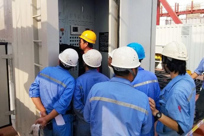
After-sales service team stationed at customer site
Complete equipment installation/coupling/training
24-hour after-sales technical support
Full Side After-Sales Service
Pre-sales technical engineers research user needs
Design personalized solutions
OEM/ODM service
Custom Development Service
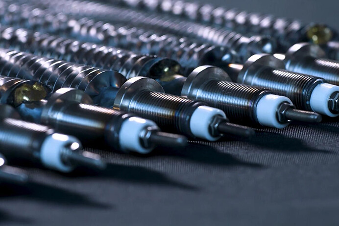
Scientific design of resistance alloy material ratio
Stable resistance value / high working temperature limit
Self-developed full batch resistance testing system
Alloy Resistor Technology
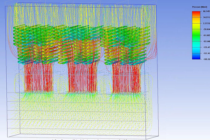
Fluid dynamics based simulation calculations
Scientific design of equipment heat distribution and release
Thermal Simulation Technology
Circuit design / mechanical design / insulation design
Software development/arm/dsp/plc development
Full Process Independent Research And Development Capability
Seaside/humid/rainy environment
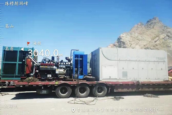
High altitude/cold/high temperature environment
Uninterrupted operation
All Day Working Capability
Service For International Famous Brand Generator Sets
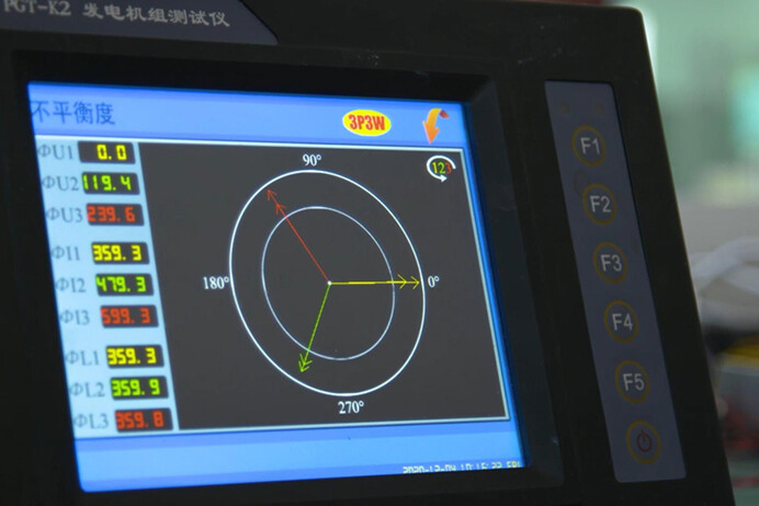
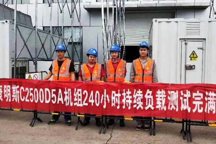
240 Hours Continuous Uninterrupted Test
Continuous Trouble-Free Operation
Electrical/mechanical strength/vibration test
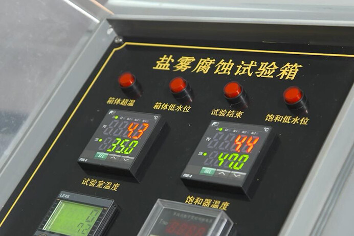
Air volume/salt spray/rain/high and low temperature test
Electromagnetic compatibility/voltage resistance/aging test
Comprehensive Quality Control


Please give us a message
