

Related content
- Oct 23, 2026Sunwin WN-18 18kW Rack-Mounted Air Cooled Load BankThe Sunwin WN-18 is an 18kW rack-mounted air cooled load bank with a reliability rate unrivaled on the market, specifically designed to support airflow testing and cooling system verification within the facility. With three-phase 400Vac input and 18kW rated power, it precisely simulates the heat generation and airflow characteristics of IT equipment through adjustable airflow and real power loading, providing reliable evidence for data center airflow management and heat dissipation verification.
Powered by 10 forced-air cooling fans with an airflow volume of ≥5508 m³/h, the WN-18 offers flexible airflow adjustment from 0 to 100% (tolerance ±2%), and with fin-type heating resistive tubes and multiple temperature protections, it is widely used in data centers, generators, power systems, new energy sources and laboratory testing. - Oct 22, 2026Sunwin WN-6 6kW Rack-Mounted Load BankThe Sunwin WN-6 is a 6kW rack-mount resistive load bank designed for low-power equipment test scenarios. Adopting a 6U rack-mount form factor, it supports dual-channel single-phase AC230V input with a maximum of 3kW per channel and a total rated power of 6kW.
By combining 0.5kW, 1kW and 1.5kW load units, the WN-6 achieves fine loading steps of 0.5kW, making it suitable for performance verification, factory inspection and maintenance testing of small-scale generators, UPS units, power modules, inverters and other AC power-supply devices. - Oct 21, 2026Sunwin 50kW AC Liquid-Cooled Rack Mounted Resistive Load BankExplore Sunwin's 50kW rack-mount AC liquid-cooled load bank for server thermal, cooling system, UPS and generator testing. Features include Modbus TCP monitoring, 75 L/min cooling flow and automatic unloading protection.
- Oct 20, 2026Sunwin WN-240L 240kW AC Liquid-Cooled Resistive Load BankThe Sunwin WN-240L is a 240kW high-power AC programmable liquid-cooled load bank designed for performance testing, burn-in testing and maintenance of power sources such as generator sets, UPS systems, solar inverters, energy storage systems and industrial electrical equipment. Its core advantage lies in an advanced closed-loop liquid cooling system, delivering 240kW of continuous load capacity with exceptional stability and low noise.
Equipped with intelligent sensors and dual control interfaces (local HMI touch screen + remote PC control), and supporting three-phase 380/400/415/480/690Vac wide voltage levels, the WN-240L ensures precise, reliable and safe testing in demanding industrial environments, especially in indoor or space-constrained test scenarios.
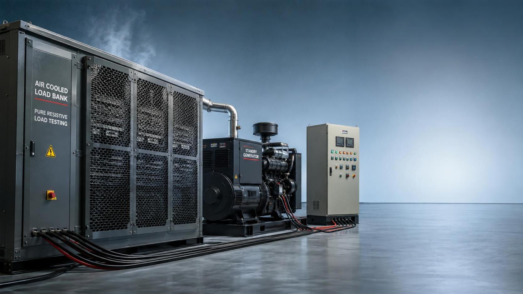
What Pure Resistive Testing Actually Tells You
A resistive load bank is the right choice when the question is straightforward: can this power source deliver its rated real power, remain stable under demand, and reject the heat created by that demand? For generators, UPS systems, battery strings, power distribution equipment, and related controls, that is often the first question that needs answering during commissioning or maintenance.
The load bank creates a controlled electrical demand by converting electrical energy into heat through resistance elements. Because the load is largely unity power factor, the source supplies real power without needing to manage the reactive effects associated with motors, transformers, or capacitor-heavy equipment. That simplicity is its practical value. Test results are easier to interpret when voltage, frequency, current, temperature, alarms, and fuel or battery behavior are being observed against a known kW load.
Pure resistive testing is not a complete replica of every facility load. A data center, manufacturing line, hospital, telecom site, or commercial building may contain substantial inductive and nonlinear loads. Still, a Resistive Load Bank is often the correct starting point because it verifies the power system's ability to produce and distribute usable real power under controlled conditions before more complex load behavior is introduced.
When a Resistive Load Bank Is the Right Tool
Resistive testing fits best when the equipment under test must demonstrate stable kW capacity and when the immediate concern is whether it can support expected demand. It is particularly useful when the real site load is unavailable, too variable, too valuable to risk during testing, or too small to exercise the equipment meaningfully.
A standby generator is a common example. Running it unloaded may confirm that the engine starts and the controls respond, but it does not prove that the generator can carry a substantial electrical load. A controlled resistive test can expose overheating, weak fuel delivery, governor instability, poor voltage regulation, cooling limitations, connection problems, or protection settings that only become visible when current is flowing.
The same logic applies to UPS equipment. A UPS may appear healthy while serving a lightly loaded installation, yet its inverter, batteries, bypass path, internal connections, and cooling system may behave differently at a higher demand level. A resistive load bank allows an operator to apply planned steps of load and observe transfer behavior, voltage stability, alarm response, and thermal conditions without placing business-critical equipment at risk.
For battery systems, resistive discharge testing can provide a controlled way to assess whether the battery assembly can sustain a defined current or power demand for a specified period. The interpretation must be careful: the result depends on discharge rate, ambient temperature, battery age, state of charge, cable resistance, and the test endpoint. Even so, a managed resistive load is far more informative than relying only on open-circuit voltage or a brief functional check.
- Generator commissioning: confirming kW output, voltage and frequency stability, cooling performance, control response, and protection operation.
- Periodic generator exercise: loading standby equipment when the normal facility demand is insufficient to exercise it properly.
- UPS commissioning and maintenance: checking inverter capacity, battery runtime behavior, bypass operation, and heat rejection under controlled demand.
- Battery discharge tests: applying a repeatable electrical load to evaluate available performance under a relevant discharge profile.
- Distribution system checks: verifying feeders, breakers, switchgear, bus connections, and cable routes under planned current levels.
- Factory or site acceptance testing: demonstrating that a packaged power system can carry a defined real-power load before it enters service.
Why “It Runs Unloaded” Is Not a Meaningful Pass Condition
Many power systems can start, synchronize, or remain energized with little or no load while still having weaknesses that matter under service conditions. The electrical and mechanical stresses at meaningful load are different. Current increases conductor heating and voltage drop. Cooling systems must reject more heat. Engines must supply more torque. Power electronics must switch and dissipate more energy. Connections that appear acceptable during a visual inspection may reveal abnormal heating when loaded.
For a generator, low-load operation can also provide a misleading picture of engine health. The exact implications depend on the engine design, duty cycle, fuel system, and manufacturer guidance, but a system that spends most of its time lightly loaded is not being challenged in the way it would be during an outage. A planned load test gives maintenance teams a defined window in which to observe behavior at selected load steps rather than infer capacity from an idle run.
That does not mean every test must reach nameplate rating or run for the same duration. The appropriate test profile depends on the purpose. A commissioning test may require higher load levels and a longer hold period than a routine exercise. A battery test may focus on a defined discharge schedule. A breaker or cable investigation may be aimed at one feeder and a specified current level. The load bank should support the test objective, rather than turning the test into a generic “full load” event with no clear acceptance criteria.
What a Resistive Test Can Reveal, and What It Cannot
A resistive load provides a clean baseline. It can show whether a source maintains voltage and frequency as real power demand rises. It can reveal unstable control loops, temperature rise, inadequate airflow, fuel-system limitations, weak battery capacity, unexpected trips, poor load sharing between parallel generators, and high-resistance connections that heat under current.
It is also useful for testing the physical path between the source and the load bank. When the connection arrangement reflects the intended service path, the test may exercise generator terminals, feeder cables, circuit breakers, switchgear, transfer switches, busways, connectors, and protective devices. A test that bypasses most of the distribution system may still be useful, but it answers a narrower question.
Its limitation is equally important: a pure resistive load does not test power factor capability, reactive power response, harmonic interaction, motor starting behavior, or the transient characteristics of nonlinear electronic loads. A generator that performs well at a resistive 1.0 power factor load may still need further evaluation if the planned installation includes large motors, variable-frequency drives, rectifiers, capacitor banks, or sensitive electronic loads.
That is why resistive testing should be viewed as a focused verification method rather than a universal simulation of a facility. It answers the real-power and thermal-capacity question well. It does not eliminate the need to consider the actual load profile where reactive or nonlinear behavior is material.
Choosing the Test Profile Before Choosing the Load Bank
Selection often starts with load-bank kW rating, but capacity alone does not define a useful test. The first decision should be the test profile: how much load will be applied, in what increments, for how long, at what voltage and frequency, and through which electrical connection point.
For a generator test, the target may be a series of load steps that allows the operator to observe voltage dip, frequency recovery, exhaust condition, coolant temperature, fuel behavior, and alarm response. For a UPS test, the schedule may include normal inverter operation, battery operation, bypass transfer, and restoration. For a battery system, the chosen discharge rate must correspond to the operational question. A short, high-current discharge and a longer, lower-current discharge can produce very different indications of available battery performance.
Increment resolution matters because it determines how closely the applied demand can match the test plan. A load bank made only of large steps may be adequate for a broad capacity test, but it can make it difficult to hold a precise target load or investigate the point at which a control issue appears. Smaller load steps allow more controlled adjustments, especially when testing equipment with a modest rating or when the test requires a specific percentage of expected operating load.
Voltage and phase configuration must be matched carefully. A three-phase load bank may be designed for a particular voltage range and frequency, while the equipment being tested may have different nominal values, grounding arrangements, or connection requirements. Applying an incompatible configuration can produce incorrect loading, trigger protection, or create an unsafe setup. The test connection should be engineered around the actual system, including cable ratings, termination method, isolation points, fault protection, and available space for safe operation.
Air-Cooled, Portable, and Permanent Installations
Physical deployment affects whether a resistive test is practical. Air-cooled load banks are widely used because the generated heat can be dissipated through forced airflow. They may be installed in fixed outdoor positions, mounted in racks or enclosures, or supplied in portable formats for temporary work. The best arrangement depends less on appearance than on access, heat discharge, noise tolerance, cable routing, and how often the test will occur.
A portable unit can be useful where several sites need periodic testing or where a temporary commissioning load is required. It introduces logistical questions: transport access, placement surface, clearance around air inlets and outlets, weather exposure, cable length, and the safe movement of high-current conductors. A permanently installed bank removes much of that setup burden for recurring tests, but it should be sized and located with maintenance access and exhaust air management in mind.
Heat is not an incidental byproduct. It is the operating principle. A 500 kW resistive load bank ultimately releases approximately that amount of electrical power as heat while it is energized. Locating the unit near ventilation intakes, occupied areas, combustible materials, temperature-sensitive equipment, or restricted air paths can turn an otherwise sound electrical test into a site problem. The test plan needs to account for airflow direction, clearance, ambient conditions, and personnel access before the bank is energized.
Common Assumptions That Lead to Weak Tests
One common assumption is that testing at any load level proves the rating of the power source. A light load may confirm basic operation, but it may not exercise the limiting components. Conversely, applying the maximum available load without a purpose can obscure useful observations and impose unnecessary stress. A defined load schedule with measurements and expected responses produces more usable information than either extreme.
Another assumption is that a load bank test automatically verifies the entire emergency power system. It only verifies the equipment and path that are actually included. If the load bank is connected directly at generator terminals, the test may say little about downstream transfer switches, feeder runs, distribution boards, or final branch circuits. If it is connected at the building distribution point, it can test more of the installation, but the connection arrangement and protective coordination deserve more attention.
It is also easy to treat a pass/fail indication as the whole result. A system may complete a test without tripping while still showing warning signs: rising temperature, unstable frequency, uneven current sharing, unusual noise, slow control response, or repeated alarms that clear after the load is removed. These observations should be evaluated in context, documented, and compared with equipment requirements and the stated acceptance criteria.
When Pure Resistive Testing Should Be Supplemented
Consider a more representative test method when the intended load has a substantial reactive or nonlinear component. Motor-driven systems may demand significant kVAr and impose starting transients. Large variable-frequency drives, rectifier systems, IT power supplies, and other electronic equipment can introduce harmonics and rapid changes in demand. In those cases, reactive load banks, combined resistive-reactive banks, or carefully controlled testing with representative equipment may provide a more complete picture.
There is no conflict between resistive and reactive testing. They answer different questions. A resistive bank establishes whether the source can deliver real power and handle the associated thermal load. Reactive testing examines voltage regulation and excitation performance under power-factor demand. A combined approach is justified when the site load profile makes both questions operationally important.
For many commissioning and maintenance decisions, the sensible sequence is to begin with a controlled resistive test, confirm the basic capacity and stability of the source, then add more representative loading only where the installation's load characteristics require it. That approach keeps the test understandable, makes faults easier to isolate, and avoids claiming that a simple load test proves behavior it was never designed to simulate.
A Resistive Load Bank earns its place when the test objective is clear: verify dependable real-power delivery under a known electrical demand. Used with an appropriate rating, connection plan, load schedule, and observation method, it turns an uncertain assumption about standby capacity into evidence that can support commissioning, maintenance, and operating decisions.




Please give us a message
