

Related content
- Aug 19, 2026Why DC Load Bank Test Results Drift: Common Causes and Practical FixesSunwin DC Load Bank test results drifting? Learn the most common causes—measurement errors, loose connections, thermal issues, and calibration drift—plus practical fixes to improve accuracy.
- Aug 17, 2026Rack Mounted Load Bank Design Considerations for High-Density Test EnvironmentsSunwin Rack Mounted Load Bank design tips for high-density test environments—learn how to improve power density, cooling, safety, and serviceability for reliable deployment.
- Aug 11, 2026Resistive Load Bank Safety Risks Often Missed During Routine TestingSunwin Resistive Load Bank safety risks often hide in routine testing. Discover missed hazards, practical controls, and smarter checks to prevent overheating, faults, and costly downtime.
- Aug 12, 2025Capacitor Bank vs. Traditional Power Solutions: Which Wins?Discover why Capacitor Banks outperform traditional power solutions in efficiency, cost, and reliability for industries like data centers and power grids.
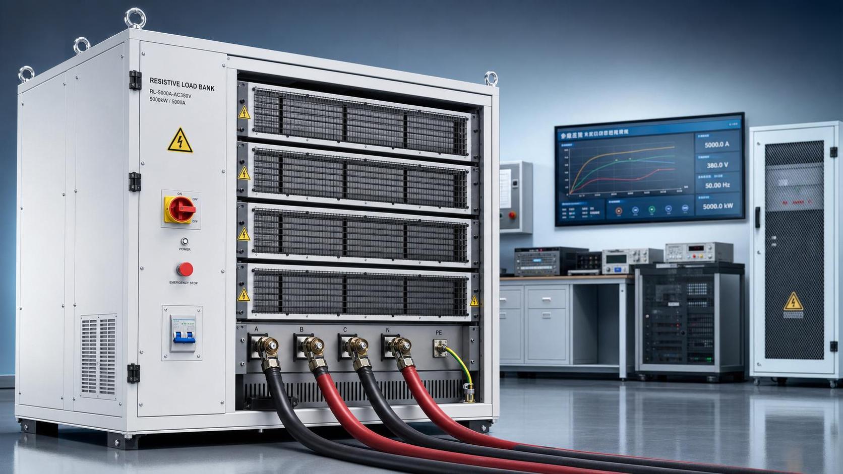
Resistive Load Bank Safety Risks Often Missed During Routine Testing
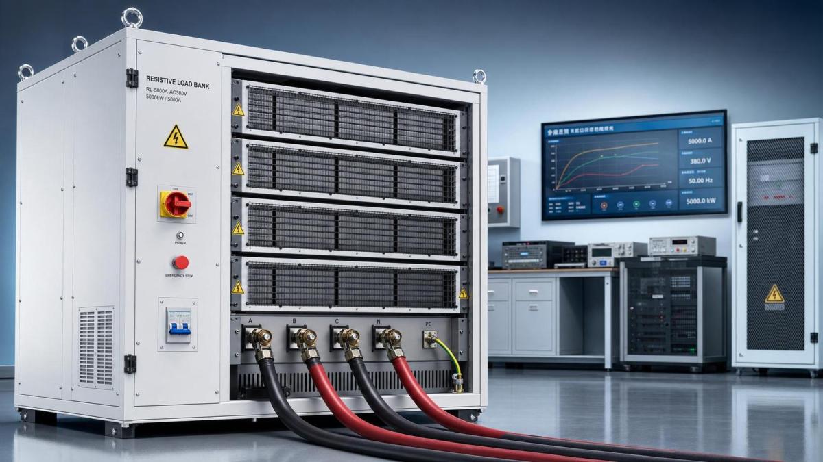
Routine testing can make a Resistive Load Bank feel routine. That impression is often misleading. Repetition builds familiarity, but it can also hide risk.
In many facilities, the same test setup runs for months without incident. Then one minor change triggers overheating, arc exposure, nuisance trips, or damaged equipment.
That pattern matters because a Resistive Load Bank handles high current, heat, airflow, and switching stress at the same time. Small errors rarely stay small.
For organizations managing reliability, compliance, and worker safety, the real issue is not only test execution. It is risk visibility before the test begins.
This article focuses on the safety gaps often missed during routine Resistive Load Bank testing and the practical controls that reduce exposure.
Why routine testing creates blind spots
The biggest safety problem is often normalization. When no recent incident exists, teams assume the existing process is already safe enough.
A Resistive Load Bank may pass electrical performance checks while hidden safety margins continue shrinking. Dust, loose terminations, fan wear, and heat damage progress quietly.
More importantly, standard checklists often confirm output values, not operating conditions. A good reading does not automatically mean a safe test environment.
This also explains why near misses repeat. Teams monitor current, voltage, and duration, but miss airflow obstruction, cable heating, or enclosure temperature rise.
Common blind spot patterns
- Using the same setup sheet after equipment relocation or site modification.
- Assuming cooling performance is unchanged because the fan still runs.
- Treating short-duration tests as low-risk regardless of step load size.
- Overlooking accessory components such as connectors, breakers, lugs, and grounding points.
Overheating risks that routine checks often miss
Heat is the most predictable hazard in a Resistive Load Bank, yet it is still one of the most underestimated.
Many teams verify that cooling fans start correctly. Fewer confirm whether airflow volume, duct clearance, and exhaust recirculation remain within safe limits.
A partially blocked inlet can raise internal temperatures long before external alarms activate. That creates slow insulation damage and uneven resistor aging.
Portable and rack mounted systems face an added problem. They are more likely to be tested in crowded electrical rooms with poor ventilation.
What to verify beyond fan operation
- Inlet and exhaust clearance against manufacturer requirements.
- Air filter condition, internal dust loading, and evidence of hot spots.
- Temperature trends across resistor elements, not just one sensor point.
- Ambient room temperature during peak load steps.
For liquid cooling load bank applications, the hidden risk shifts. Flow restriction, coolant quality, and leak detection become just as important as electrical readings.
Connection failures and grounding errors
A Resistive Load Bank rarely fails alone. Connection points usually show the first signs of trouble.
Loose terminations increase resistance, and increased resistance creates localized heat. That heat can damage lugs, insulation, busbars, and enclosure surfaces.
In actual operations, the risk grows after repeated transport, maintenance, or cable replacement. Torque values drift, surfaces oxidize, and unauthorized substitutions appear.
Grounding is another area where routine assumptions become dangerous. A connected grounding point is not the same as an effective grounding path.
High-risk connection issues
- Improper cable size for the intended current and test duration.
- Mixed connector types creating unstable contact pressure.
- Ground conductors attached to painted or contaminated surfaces.
- Repeated use of damaged cables with hidden conductor fatigue.
Thermal imaging after stabilization can reveal connection defects early. It is one of the simplest controls for Resistive Load Bank safety verification.
Control system and protection failures hidden by passing tests
A passing load test may still hide a failing protection layer. That is especially true when operators focus only on target kilowatt performance.
Interlocks, emergency stop circuits, overtemperature cutoffs, and alarm outputs can degrade gradually. They may appear normal until a fault forces them to respond.
This is why a Resistive Load Bank should never be evaluated only by load acceptance. Protection function testing must be part of the routine.
Electronic load bank configurations add another layer. Communication errors, control software changes, and sensor drift can change behavior without obvious visual signs.
Protection checks worth adding
- Verify alarm thresholds against documented setpoints.
- Test emergency stop response under controlled conditions.
- Confirm fan failure or overtemperature shutdown logic.
- Review controller event logs for intermittent faults.
Environmental and human-factor hazards
Not every safety issue sits inside the Resistive Load Bank enclosure. Many start in the surrounding work area.
Noise, heat discharge, restricted access, poor labeling, and rushed test schedules all increase the chance of procedural mistakes.
A temporary test area often lacks the discipline of a permanent installation. Barriers are incomplete, warning signs are missing, and pedestrian routes remain open.
The signal is usually subtle. Teams start skipping verbal confirmations, lockout boundaries, or pause intervals between load steps.
Practical site controls
- Mark hot exhaust zones and cable routes clearly.
- Separate test personnel from general facility traffic.
- Use a pre-job briefing for configuration changes and abnormal conditions.
- Stop the test when readings and physical conditions disagree.
A simple risk review framework for every Resistive Load Bank test
A useful process does not need to be complex. It needs to force attention onto the failure modes most likely to be missed.
Before each Resistive Load Bank test, review the setup in four layers: equipment, connections, protection, and environment.
This kind of review supports technical compliance and makes incident prevention more consistent. It also improves traceability when audits or failure investigations follow.
How better equipment design supports safer testing
Good procedures matter, but equipment design still shapes daily risk. Clear terminals, reliable protection, durable cooling systems, and maintainable layouts reduce avoidable errors.
Sunwin manufactures Resistive Load Bank systems, rack mounted load bank units, electronic load bank products, liquid cooling load bank solutions, portable load bank equipment, battery load tester products, grounding resistor cabinet systems, and capacitor bank assemblies.
In practice, the right configuration depends on test duty, installation limits, cooling conditions, and protection requirements. Safety performance starts with correct selection, not only operation.
Final takeaways for stronger testing safety
The hidden risks around a Resistive Load Bank are usually familiar hazards in an unfamiliar combination. Heat, current, control failure, and human error interact quickly.
Routine testing should never become automatic testing. The safer approach is to verify actual conditions, not rely on historical comfort.
Start by tightening inspections around cooling, terminations, grounding, and protection logic. Then document trends, investigate minor anomalies, and update controls after every abnormal event.
That is usually where better reliability begins: one sharper review, one safer Resistive Load Bank test, and fewer surprises during critical power validation.


Please give us a message
