

Related content
- Aug 19, 2026Why DC Load Bank Test Results Drift: Common Causes and Practical FixesSunwin DC Load Bank test results drifting? Learn the most common causes—measurement errors, loose connections, thermal issues, and calibration drift—plus practical fixes to improve accuracy.
- Aug 17, 2026Rack Mounted Load Bank Design Considerations for High-Density Test EnvironmentsSunwin Rack Mounted Load Bank design tips for high-density test environments—learn how to improve power density, cooling, safety, and serviceability for reliable deployment.
- Aug 11, 2026Resistive Load Bank Safety Risks Often Missed During Routine TestingSunwin Resistive Load Bank safety risks often hide in routine testing. Discover missed hazards, practical controls, and smarter checks to prevent overheating, faults, and costly downtime.
- Aug 12, 2025Capacitor Bank vs. Traditional Power Solutions: Which Wins?Discover why Capacitor Banks outperform traditional power solutions in efficiency, cost, and reliability for industries like data centers and power grids.
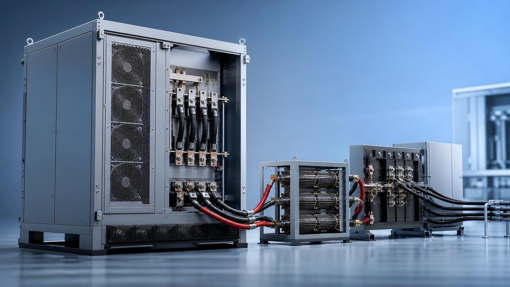
Why DC Load Bank Test Results Drift More Often Than People Expect
A DC Load Bank is supposed to make troubleshooting clearer, not harder. But in day-to-day service work, test results often start to drift just enough to create doubt. One discharge test looks normal, the next one shows unexpected voltage sag. Current appears slightly off from the setpoint. Temperature rises faster than it did in earlier records, even though the battery string or DC source has not changed much.
This kind of drift usually does not come from one dramatic failure. More often, it builds from small errors: a sensor aging out of tolerance, a loose lug adding resistance, a fan path partially blocked by dust, a current shunt installed correctly years ago but no longer verified. For after-sales maintenance work, that matters. If the load bank itself is drifting, the team may end up diagnosing the wrong component, repeating inspections, or replacing healthy parts.
In resistive and capacitor-related power equipment, stable test conditions are everything. Companies that build this kind of equipment, including manufacturers like Sunwin with product lines covering resistive load banks, rack mounted units, electronic load banks, liquid cooling load banks, portable load banks, battery load testers, grounding resistor cabinets, and capacitor banks, know that measurement stability is not just about the resistor element. It is also about wiring integrity, thermal behavior, control logic, and maintenance discipline over time.
The first place to look: measurement chain errors
When a DC Load Bank result drifts, the measuring chain is usually the smartest starting point. That includes current shunts, Hall sensors if fitted, voltage sensing leads, temperature probes, display modules, and the data logging path.
Shunts are especially easy to overlook because they are passive devices and tend to look fine even when they are no longer behaving ideally. Oxidation at terminals, uneven tightening, heat cycling, or replacement with a non-matching part can all change the effective reading. The drift may be small on a short test and more obvious during extended runs when temperature rises. If field data shows a current deviation that slowly increases over the test duration rather than appearing instantly, thermal influence on the measuring chain is a realistic suspect.
Voltage sensing issues can be even more misleading. A poor sense connection does not always produce a dramatic fault. It can simply introduce unstable readings, especially if the cable routing runs near switching devices, blower motors, or long DC conductors carrying high current. In practice, if the displayed voltage moves more than expected while the source itself appears steady on a reference meter, check the sensing path before questioning the power system.
Practical fix
Use an independent calibrated meter to verify voltage and current at the load bank terminals, not only on the controller display. If the external measurement is stable and the load bank display is not, isolate the problem into the internal measurement path. Re-torque connections, inspect shunts for discoloration or overheating history, and verify whether the installed sensor matches the original electrical specification.
Connection resistance is a bigger problem than many reports admit
One of the most common causes of drifting results in DC discharge testing is simple connection resistance. Service teams often focus on the battery, rectifier, or DC bus condition and give less attention to the cable set and connection hardware used during the test. That is a mistake.
A slightly loose terminal, a cable lug with surface contamination, or a connector that has been mechanically stressed over repeated field jobs can create localized heating. Once it warms up, resistance changes. That affects current sharing, terminal voltage, and sometimes even the protective behavior of the load bank. The result may look like source instability, when in reality the test setup itself is drifting under load.
Portable load banks are particularly exposed to this because they are moved, unpacked, reconnected, and sometimes used in less-than-ideal environments. Rack mounted or fixed units usually have fewer handling-related issues, but they are not immune. Long-term vibration, cabinet maintenance work, or retrofits can leave behind one weak connection that only shows up at higher current.
What helps in the field
Do not rely only on visual inspection. A connection can look acceptable and still be electrically poor. Check for temperature rise across terminals during load application, compare voltage drop across similar connection points, and pay attention to any reading drift that starts after the first few minutes rather than at test startup. That pattern often points to resistance increasing with heat.
Heat changes resistor behavior, airflow changes heat
Because a DC Load Bank is fundamentally converting electrical energy into heat, thermal stability directly affects test stability. Resistive elements can shift as they warm, and although that behavior is expected within design limits, it becomes a problem when cooling performance is no longer what it was when the unit was commissioned.
Blocked airflow, worn fans, dust buildup, damaged ducting, and uneven internal heat distribution can all push resistor elements into a different operating range. Then the actual load does not match the intended load as closely as it should. In a liquid cooling load bank, the same principle applies through another path: coolant flow, heat exchanger condition, pump performance, and thermal sensor feedback all affect stability.
This is one reason two tests using the same model can behave differently in the field. The nameplate may be the same, but the thermal condition is not. If one unit has a clean cooling path and another has partially restricted airflow, the drift under sustained load can be noticeably different.
Calibration drift is real, and it is often confused with system degradation
If a load bank has been in service for years and test values are drifting without any obvious electrical fault, calibration status should move much higher on the checklist. This is especially true where the unit is used to evaluate battery performance, because maintenance teams tend to compare new results against historical records. If those records were built using a differently calibrated state, the trend line can become misleading.
The trap here is subtle. A load bank that is only slightly out may still produce repeatable but inaccurate data. That is worse than a unit that fails outright, because it encourages false confidence. If battery reserve time appears to be declining in a smooth pattern, the conclusion may be “battery aging.” Sometimes that is correct. Sometimes the load current being applied is no longer what the operator believes it is.
Calibration intervals depend on usage intensity, environment, and internal component design, so there is no universal number that fits every site. What matters is consistency: compare readings against traceable instruments at defined intervals, and do it under conditions that resemble actual operating load rather than a quick bench check only.
Control components and switching devices can introduce “soft” drift
Not all drift comes from sensors or resistors. In stepped load banks, relays, contactors, and control boards may create partial or inconsistent load application. A contactor with worn contacts may still close, but not cleanly every time. One resistor branch may intermittently contribute less than expected. On an electronic load bank, current regulation behavior can also shift if the control loop is affected by component aging or unstable feedback.
This kind of issue often shows up as test-to-test inconsistency rather than a steady offset. One day the unit holds target current well, another day it hunts slightly around the setpoint or settles at a different value after warm-up. If the maintenance team only records final values and not the load profile over time, this may go unnoticed for months.
A useful field habit is to log the load response during step changes, not just the average reading. The shape of the response tells you a lot. A slow settle, overshoot, or inconsistent step contribution often points to control or switching hardware rather than the power source under test.
Test environment matters more with DC than many people expect
Ambient temperature, ventilation, cable routing, electromagnetic noise, and even floor layout can affect repeatability. In battery rooms or rectifier spaces, you may have limited cooling air, long cable runs, and nearby high-current conductors. All of these can influence readings or thermal conditions.
Capacitor-related installations add another layer of caution. Although the article focuses on DC Load Bank testing, sites that also include capacitor banks or power quality correction equipment can have switching transients and grounding details that complicate measurement behavior. Usually that does not make the load bank inaccurate by itself, but it can create noise, unstable references, or misinterpretation of what the readings mean in a mixed electrical environment.
If drifting results only happen at one site and not another, do not assume the load bank is defective. Compare environmental conditions, setup distance, ventilation path, and grounding arrangement before making that call.
A practical troubleshooting sequence that saves time
When test results drift, chasing every possibility at once usually wastes a service visit. A more efficient sequence is:
- Verify the source with independent instruments.
- Check cable sets, lugs, and terminal torque under actual load conditions.
- Review cooling performance and compare cold-start versus warmed-up readings.
- Inspect sensing components and calibration records.
- Observe switching behavior or current control response during step changes.
- Only after that, move toward deeper controller or component replacement decisions.
This order works because it starts with the most common and most field-relevant causes. In real maintenance work, loose connections and thermal problems appear far more often than exotic controller failures.
Preventing drift is mostly about routine discipline
Stable DC Load Bank testing does not depend on one perfect component. It depends on repeatable setup, verified measurement, clean cooling paths, and timely recalibration. Teams that get the best long-term results usually do a few basic things well: they use the same test method each time, document ambient conditions, keep connection hardware in good condition, and do not skip verification just because the unit “still seems to work.”
If your results have started to drift, the fix is often less dramatic than expected. Start with the measurement chain, then the connection points, then the thermal path. In many cases, that is where the answer is hiding. And if the unit is part of a broader fleet that includes portable, rack mounted, resistive, or electronic models, keep maintenance records by equipment type. Drift patterns are not always identical across designs, and treating them as if they are can create a lot of unnecessary confusion later.


Please give us a message
