

Related content
- Sep 22, 2026Capacitor Bank Sizing to Improve Power Factor Without Creating Harmonic RisksSunwin Capacitor Bank sizing made practical: improve power factor with measured data, smart switching, and harmonic checks that prevent resonance risks.
- Sep 20, 2026Electronic Load Trends Shaping Battery and EV Power-Test Investment DecisionsSunwin Electronic Load trends are reshaping battery and EV power-test investments. Explore smarter, scalable solutions for realistic testing, energy efficiency, and reliable data.
- Sep 14, 2026What to Check Before Buying a Rack Mounted Load Bank for Data Center TestingSunwin Rack Mounted Load Bank buying guide for data center testing: compare electrical ratings, load steps, cooling, controls, safety, and installation needs before ordering.
- Sep 09, 2026Resistive Load Banks Explained: When Pure Resistive Testing Is the Right ChoiceSunwin Resistive Load Bank testing explained: discover when pure resistive loads verify generator, UPS, battery, and power-system capacity with confidence.
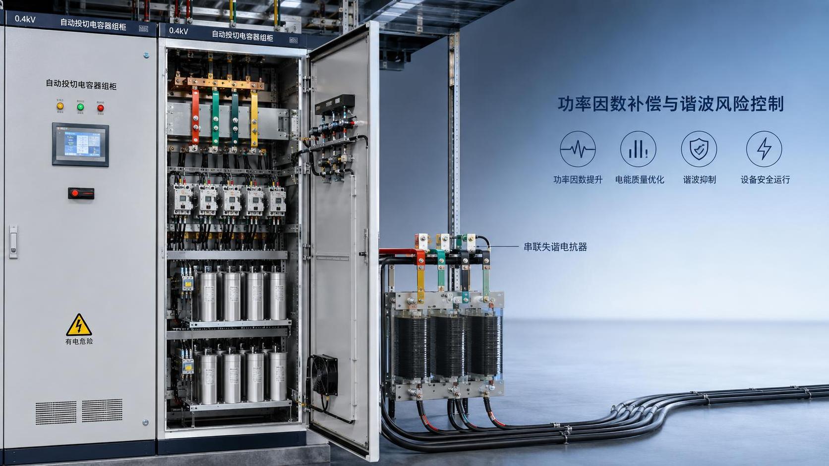
A capacitor bank should be sized from measured reactive demand and a defined operating power-factor target, then checked against the network harmonic spectrum before equipment is selected. Starting with a catalog kvar value or sizing only from the transformer rating can correct the wrong condition, create leading power factor at light load, or place the capacitor bank near a harmonic resonance point.
The practical objective is not to install the largest possible compensation system. It is to supply only the reactive power that the electrical system needs across its normal operating range while keeping capacitor current, voltage stress, and harmonic amplification within acceptable limits.
Start with the operating condition, not the nameplate load
Power factor correction is often discussed as though the facility has one fixed load. Most systems do not. Motor groups cycle, welding equipment operates intermittently, HVAC loads vary with demand, and variable-frequency drives may remain energized while their mechanical load changes. A capacitor bank sized from connected kW instead of measured demand can therefore be substantially oversized.
Collect interval data at the point where compensation will be installed or where the utility measures power factor. The useful inputs are real power (kW), reactive power (kvar), apparent power (kVA), power factor, voltage, and load variation over representative production and low-load periods. Measurements should also capture conditions when major nonlinear loads are active.
The initial compensation requirement can be calculated using:
Required capacitor kvar = kW × (tan φ1 − tan φ2)
Here, φ1 is the angle associated with the measured power factor and φ2 is the angle associated with the desired power factor. This calculation is a starting point, not a final equipment specification. It indicates how much reactive power must be reduced at one operating point; it does not decide whether the bank should be fixed, switched, detuned, or distributed.
For example, a site with a stable induction-motor load may have a predictable kvar requirement. A plant whose load falls sharply outside production hours may require smaller switched steps, because compensation that is appropriate during full production can become excessive when only controls, lighting, and lightly loaded drives remain online.
Choose a target power factor with operating margin
A target close to unity is not automatically the best design target. Capacitors continue supplying reactive power whenever they are connected, while inductive demand can fall. If the bank remains connected after the load drops, the system may become leading rather than simply less lagging.
Leading power factor can raise voltage, interfere with generator or transformer operation, and cause automatic controllers to hunt between steps. It can also distort the measurement used by a power factor controller, particularly where nonlinear loads are significant.
A better target is one that meets the commercial or operational requirement while leaving room for load movement and capacitor tolerance. The selected target should be evaluated at high load, typical load, and minimum foreseeable load. This is especially important when a facility has standby generation, seasonal process equipment, or large motor groups that are frequently switched.
Fixed, automatic, and distributed compensation solve different problems
Automatic banks are often selected because they can follow changing demand, but their step arrangement matters more than the number of stages. Very large steps make control coarse and can overshoot the target. Very small steps may increase switching activity without improving the result. The smallest step should reflect the normal variation in reactive demand, while the total installed kvar should cover the expected maximum requirement with appropriate margin.
Where large motors start and stop independently, local compensation may reduce feeder current and voltage drop. However, capacitors connected directly with a motor need careful switching coordination. A motor can become self-excited under certain disconnection conditions if capacitors remain connected, so the capacitor switching method must follow the motor-control arrangement rather than being treated as a separate installation.
Harmonic assessment determines whether a standard capacitor bank is suitable
Capacitors have lower impedance as frequency rises. This makes them useful for fundamental-frequency reactive power, but it also means they can attract harmonic current. In a network containing variable-frequency drives, rectifiers, UPS systems, arc equipment, switched-mode power supplies, or other nonlinear loads, a plain capacitor bank can become a harmonic current path.
The major concern is parallel resonance. The system inductance, largely associated with transformers and upstream supply impedance, interacts with the capacitance of the bank. At a particular frequency, their combined impedance can become high, allowing harmonic voltage distortion to increase. Near a dominant harmonic frequency, capacitor current can rise sharply and equipment stress can escalate.
This is why capacitor capacity cannot be finalized from power factor alone. A harmonic survey should identify the voltage and current distortion present during relevant loading conditions, the dominant harmonic orders, transformer impedance, available fault level or equivalent supply strength, existing capacitors, and any planned changes to drive or rectifier capacity. The result is used to assess resonance locations and capacitor duty.
Do not assume that a low measured distortion value at one moment eliminates harmonic risk. Harmonic conditions can change with production state, supply configuration, generator operation, and the number of nonlinear loads in service. A measurement taken during low drive loading may not represent the condition when the facility is operating at full output.
When detuned reactors are the appropriate choice
A detuned capacitor bank places reactors in series with capacitor steps. The reactor shifts the bank’s resonant frequency away from problematic harmonic orders and limits the inrush and harmonic current seen by the capacitors. It is commonly considered where nonlinear loads form a material portion of demand or where harmonic measurements and network calculations indicate resonance exposure.
Detuning is not the same as harmonic filtering. A detuned bank is primarily power factor correction equipment designed to avoid harmonic amplification. If the system must reduce a particular harmonic component to meet a defined power-quality objective, a purpose-designed passive filter, active harmonic filter, or a coordinated hybrid solution may be more suitable.
Reactor selection changes the electrical duty of the capacitors. The capacitors must be rated for the resulting operating voltage, current, and thermal environment, rather than selected solely by their nominal kvar at fundamental frequency. The bank enclosure, ventilation, protection devices, contactors or thyristor switching components, and controller also need to suit the expected harmonic environment.
Common sizing errors that create avoidable problems
- Using transformer capacity as the capacitor-bank size. Transformer kVA describes capacity, not the actual reactive demand or load profile.
- Correcting a single snapshot to unity power factor. This commonly produces leading power factor when the load declines.
- Adding capacitors after a drive expansion without reassessing harmonics. New nonlinear loads can move the network into a different resonance condition.
- Using a fixed bank on a variable process. A fixed installation is appropriate only when the inductive load is genuinely stable or is switched with that load.
- Ignoring existing correction equipment. Old capacitors, locally corrected motors, and utility-side devices all affect total kvar and resonance behavior.
- Treating failed capacitor fuses as an isolated maintenance issue. Repeated fuse operation, bulging capacitors, overheated reactors, or frequent controller alarms can indicate a sizing, switching, voltage, or harmonic problem.
A practical selection sequence
- Define the correction point. Decide whether the objective is to improve the power factor at the utility metering point, reduce loading on a transformer, relieve a feeder, or support a specific motor group. These goals may require different placement.
- Measure representative electrical behavior. Record kW, kvar, power factor, voltage, load profile, and harmonic data during the operating states that matter.
- Set an achievable target. Select a target that satisfies the project objective without driving the system leading during normal light-load operation.
- Calculate the required kvar range. Use the power-factor calculation at multiple load points, not only the peak condition.
- Select the switching architecture. Choose fixed, stepped automatic, distributed, or a combination based on how reactive demand changes.
- Complete resonance and duty checks. Assess the effect of the proposed capacitance with transformer and supply impedance, then determine whether detuned reactors or filtering are required.
- Specify protection and monitoring. Include suitable isolation, short-circuit protection, discharge arrangements, temperature management, capacitor protection, and controller functions. Monitor kvar, power factor, switching status, alarms, and capacitor current after commissioning.
Commissioning should confirm more than the displayed power factor. Verify that each step operates correctly, the controller does not hunt, voltage remains controlled through switching events, and capacitor currents remain consistent with the intended duty. Repeat harmonic observations with the capacitor bank both connected and disconnected. A satisfactory result is one where correction improves operating power factor without introducing abnormal current, voltage distortion, or unstable switching behavior.
Equipment selection should follow the study, not replace it
A capacitor bank is part of a wider electrical system. Its reliability depends on the quality of the load data, network assessment, component duty ratings, installation environment, and maintenance access. For projects that also involve load testing, grounding arrangements, or power-system upgrades, coordination between these functions can prevent conflicting assumptions about source strength, switching conditions, and fault behavior.
Manufacturers such as Sunwin provide capacitor bank equipment alongside load-bank and grounding-resistor cabinet solutions. For a power-factor correction project, the useful technical discussion is not simply the nominal kvar available. It should cover the measured load profile, the presence of nonlinear loads, required switching behavior, detuning needs, installation voltage, enclosure conditions, and the monitoring required after energization.
The most defensible capacitor-bank specification is therefore a controlled outcome of measurement and system analysis: enough reactive compensation to improve the intended operating condition, divided into steps that match real load changes, and designed so that the added capacitance does not become a harmonic liability.


Please give us a message
