

Related content
- Sep 27, 2026WN-5000L 5000kVA Resistive-Inductive Load BankThe WN-5000L is a 5000kVA high-power resistive-inductive (R/L) load bank developed by Qingdao Sunwin Technologies Co., Ltd. (Sunwin). Designed for generator load bank testing, UPS load bank testing, data center load testing and power-system tests, it delivers controlled active and lagging reactive loading to fully meet power equipment load-verification requirements.
Built on the core principle of "resistive-inductive integration", the WN-5000L combines 4000kW active load with 3000kVar inductive reactive load at 0.8 lagging power factor, accurately reproducing the real operating conditions of generator sets and UPS systems. It helps customers fully verify load capacity and reliability during factory acceptance, grid-connection testing and routine maintenance. - Sep 28, 2026Grid-Connected Inverter Compliance: Essential Tests Before Solar Project HandoverGrid-Connected Inverter compliance tests for solar handover: verify protection, anti-islanding, power quality, grounding, and control settings before utility approval.
- Sep 22, 2026Capacitor Bank Sizing to Improve Power Factor Without Creating Harmonic RisksSunwin Capacitor Bank sizing made practical: improve power factor with measured data, smart switching, and harmonic checks that prevent resonance risks.
- Sep 20, 2026Electronic Load Trends Shaping Battery and EV Power-Test Investment DecisionsSunwin Electronic Load trends are reshaping battery and EV power-test investments. Explore smarter, scalable solutions for realistic testing, energy efficiency, and reliable data.
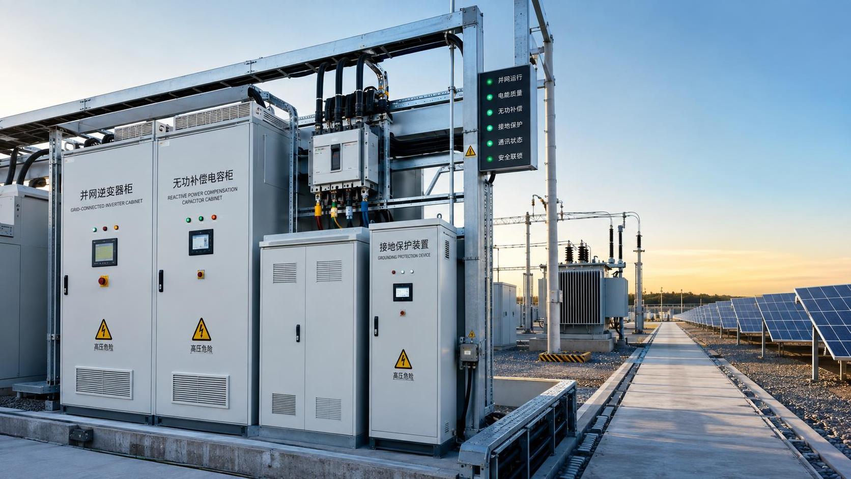
Handover Compliance Begins Before the Final Witness Test
A solar project is not ready for handover because the Grid-Connected Inverter starts, synchronizes, and produces power under favorable conditions. It is ready when the quality and safety team can show that its connection behavior remains acceptable at the grid interface, that protective functions operate in the right sequence, and that the installation will not create an avoidable hazard during abnormal conditions.
This distinction matters because many handover problems emerge after a system has already passed a basic functional run. An inverter may export expected active power while still presenting poor power factor control, excessive harmonic contribution at a weak point of connection, inadequate earthing continuity, or settings that do not match the approved interconnection study. Those issues can lead to failed utility witnessing, delayed energization, nuisance trips, damage during a fault, or disputes over whether a problem belongs to the EPC contractor, inverter supplier, or grid operator.
For quality and safety personnel, the practical question is not simply whether every possible test has been performed. It is whether the test package proves the installed system behaves as approved under conditions that could reasonably occur before and after handover. The answer depends on the local grid code, the interconnection agreement, the inverter certification basis, plant topology, and the point where compliance is measured. A disciplined test plan must connect all of those items rather than treating a factory certificate as a substitute for site verification.
Start With the Applicable Connection Requirements
Before commissioning tests are scheduled, the project team should establish a controlled list of requirements. Grid-connected equipment is often assessed against several layers of obligations: utility interconnection rules, national or regional electrical standards, approved protection settings, equipment certificates, and the project’s own design documents. These documents may use similar terms while imposing different limits, response times, or test methods.
A common source of confusion is assuming that an inverter’s product certification automatically confirms site compliance. Certification can demonstrate that a model was designed and evaluated against a defined standard configuration. It does not prove that the installed unit has the correct firmware, country code, communication configuration, external protection coordination, transformer vector group, cable arrangement, or grid support settings for a specific project.
The handover file should therefore identify, in one place:
- The approved point of common coupling and the measurement boundary for voltage, power quality, and protection performance.
- The required voltage and frequency operating ranges, including permitted ride-through behavior and disconnection thresholds.
- Active power limits, ramp-rate controls, reactive power or power-factor obligations, and any remote curtailment interface.
- Protection settings for overvoltage, undervoltage, overfrequency, underfrequency, loss of mains, and reconnection timing.
- Requirements for harmonic distortion, DC injection, flicker, phase imbalance, and voltage support where applicable.
- The documentation needed to demonstrate that the commissioned configuration matches the approved design.
This exercise is often more valuable than adding another generic test. It exposes contradictions early. For example, the utility may require a fixed power-factor target at the connection point, while the inverter is configured to regulate reactive power locally. Or the approved protection study may specify a trip delay that does not align with the default inverter protection curve. Such differences should be resolved through controlled engineering changes, not by informal field adjustment.
Verify the AC Output Under Realistic Operating Conditions
Basic start-up checks confirm polarity, insulation condition, communications, and initial synchronization. Compliance testing must go further by observing the AC output while the inverter moves through meaningful operating states. The test conditions do not need to reproduce every possible grid event, but they should reveal whether the control system, measurement channels, and protective functions behave predictably.
Active power output should be checked against the plant control strategy, inverter rating, irradiance availability, and any export limitation. Where an energy management system or plant controller is responsible for curtailment, the test should demonstrate the complete command path, including the behavior after loss and restoration of communications. A command displayed in a supervisory system is not sufficient evidence that the inverter has changed its output at the electrical connection point.
Reactive power and power factor deserve equally careful treatment. A project can satisfy an inverter-level setpoint while missing the target at the point of common coupling because transformers, cable capacitance, collector circuits, capacitor banks, and other connected equipment change the measured result. Quality teams should document where the value is measured, how instrument transformers are scaled, and whether the test was conducted at a representative output level. Low-load power factor readings can be misleading when fixed reactive elements dominate the circuit.
Capacitor banks may be part of the site’s power-factor strategy, but their operation must be coordinated with inverter reactive power control. If both systems respond independently, they can overcompensate, hunt between steps, or push voltage outside the preferred range. The handover test should show that switching logic, dead bands, delays, and controller priorities do not create unstable behavior during changing solar output.
Power Quality Cannot Be Judged From One Screen Reading
Voltage and current waveform quality should be assessed with equipment capable of recording the required parameters over an appropriate interval. A momentary display may conceal intermittent harmonic peaks, rapid control oscillation, or switching effects associated with changing output. Measurements should be traceable to the agreed connection point and taken with a clear record of plant output, network condition, and the status of major reactive components.
Harmonic evaluation is especially sensitive to the measurement location. A low distortion reading at an individual inverter terminal does not necessarily indicate acceptable contribution at the project boundary. Conversely, elevated voltage distortion at the connection point may originate partly from the supply network rather than from the solar plant. The purpose of testing is to separate these effects as far as practical, document the operating context, and determine whether the installation complies with its assigned responsibility.
Where multiple inverters operate in parallel, assess behavior with a representative number online and, where practical, through normal transitions such as block start, staged shutdown, curtailed operation, and changing reactive demand. Parallel units can interact through common control loops or a relatively weak grid. A system that appears stable with one inverter energized may behave differently as more units synchronize.
Anti-Islanding and Grid Protection Must Be Tested as a Coordinated System
Anti-islanding protection is central to safe grid connection. If a section of network becomes isolated from the utility but remains energized by distributed generation, personnel may face an unexpected live circuit and equipment can be exposed to poor voltage or frequency control. A Grid-Connected Inverter must detect loss of the grid within the required conditions and either cease energizing or follow the specifically approved ride-through response.
The testing approach must match the approved protection philosophy. In some installations, the inverter’s internal loss-of-mains function is one component of a broader scheme that includes interface protection relays, circuit breakers, communications-assisted tripping, or utility-owned equipment. Testing only the inverter menu settings leaves a major gap if the external trip path, breaker auxiliary contacts, or protection relay outputs have not been verified.
A useful handover test sequence checks both individual functions and the complete chain:
- Confirm the protection setpoints in the inverter, interface relay, plant controller, and approved study are consistent.
- Inject or simulate the relevant voltage and frequency conditions using an appropriate method for the installed protection equipment.
- Verify that the intended device trips, that the correct breaker or contactor opens, and that the inverter ceases export as required.
- Record the observed operating time, event log, breaker status, and any alarm or remote indication.
- Restore normal conditions and verify reconnection only after the required delay and synchronization checks.
Testing should include failure modes that can occur in the completed plant, not only idealized signal tests. Examples include a disconnected voltage sensing lead, incorrect phase sequence, unavailable communications, a tripped upstream breaker, or an open circuit in a remote trip circuit. The selected scenarios depend on the design, but the objective remains the same: identify a single point of failure that could leave generation connected when it should be disconnected.
Ride-through requirements require particular care. Some grid codes require generating equipment to remain connected through defined voltage or frequency disturbances, while other conditions demand rapid disconnection. Treating every disturbance as a trip test can produce a result that appears conservative but is actually non-compliant. The expected response must be taken from the governing connection requirement, including the permitted voltage-time envelope and any reactive current or active-power recovery behavior.
Grounding Is Both a Compliance Issue and a Safety Boundary
Earthing and bonding checks should not be reduced to a single resistance number. The acceptable arrangement depends on the site earthing system, fault level, transformer configuration, protection scheme, soil conditions, and local rules. A low measured earth resistance alone does not confirm that touch voltage, fault-clearing performance, equipment bonding, and surge protection coordination are adequate.
At handover, the team should verify continuity of protective conductors and bonding connections, correct termination of inverter protective earth points, integrity of the grounding electrode system, and the intended path for fault current. Where the project includes a grounding resistor cabinet, its rating, connection, monitoring provisions, and coordination with protection devices should be checked against the approved design. An incorrectly connected or bypassed grounding resistor can alter fault current substantially and change how protection devices respond.
Documentation matters here because many grounding problems are hidden after trenching, backfilling, and enclosure closure. Test records should identify test points, instruments, weather or soil conditions where relevant, and the as-built location of electrodes, conductors, joints, and accessible inspection points. This record supports later fault investigation and helps operations teams distinguish degradation from an original installation defect.
Load-Based Testing Reveals Problems That Open-Circuit Checks Miss
Inverter testing is often constrained by weather, export permission, or the availability of the upstream network. A controlled load bank can help validate portions of the electrical system when full solar generation or unrestricted grid export is unavailable. It is particularly useful for checking switchgear, cable paths, transformer loading, thermal behavior, metering, control commands, and protection coordination under known load conditions.
The test arrangement must be engineered for the direction of power flow and the equipment being evaluated. A load bank does not replicate every characteristic of a utility network, and it cannot by itself prove all grid-code functions. Its value lies in creating repeatable, measurable conditions that expose overheating, voltage drop, incorrect phase loading, unstable control response, or a mismatch between calculated and installed capacity.
Resistive load is often appropriate when the purpose is to confirm active-power capability and thermal performance. Reactive or combined loading may be required when evaluating power-factor compensation, transformer behavior, or controls expected to regulate vars. The selected load profile should reflect the compliance question. Loading a system at one steady condition may prove cable capacity but reveal little about ramp control, staged switching, or the interaction between capacitor steps and inverter var commands.
Make the Handover Package Usable After the Commissioning Team Leaves
A project can pass a witnessed test and still create operational risk if the evidence is incomplete or settings cannot be traced. The final package should allow an independent engineer or operations manager to answer basic questions without relying on memory: What was tested? Under which configuration? At what point was it measured? Which instruments were used? What settings were active? Did the observed response meet the approved requirement?
Include the signed test procedures, raw measurement records where relevant, calibrated instrument details, inverter configuration exports, protection relay settings, event logs, single-line diagrams, as-built drawings, equipment certificates, and records of deviations or approved changes. Photographs can support identification of labels, breaker positions, grounding connections, and test setup, but they should not replace electrical records.
Configuration control is especially important for inverter firmware and grid-code profiles. A compliant result can be invalidated after handover if a replacement unit is installed with a default regional profile, a controller update changes control priorities, or a technician modifies a protection threshold without updating the approved record. Locking settings where possible and defining a formal change process is part of preserving compliance, not merely an administrative preference.
The strongest pre-handover test program produces more than a pass or fail statement. It leaves a defensible connection between the grid requirement, the installed equipment, the observed electrical behavior, and the final operating configuration. That connection is what gives quality and safety teams confidence that the solar plant can be handed over without transferring hidden grid and personnel risks into operations.


Please give us a message
